Bitbanging SPI on the Raspberry Pi (via spi-gpio)
Hello all and happy holidays to everyone! I’m taking a break off work for the holidays so I have a little bit of time on my hands. I will therefore regale you with tales of my exploits!
From my last post, I talked about the somewhat “edge” case where you’d want to add (cheap) Ethernet to a Raspberry Pi, probably the A+ or Zero as the case may be. I haven’t figured out the fixed MAC thing just yet, but I’m working on it. Anyways, after some time, another edge-edge case came to me: The ENC28J60 takes up the only SPI peripheral available on the Pi, so what if you needed to use both the ENC28J60 AND some other SPI device? The Pi’s SPI peripheral has two chip selects, so it is theoretically possible to use the exact same bus while using the first chip select for the ENC28J60 (which it uses by default) and using the second chip select for the other device. However, it goes without saying that network communications require some serious computing firepower so it might cause a bit of a performance hit in general. Thinking about it some more, it became apparent that the Pi should be able to bitbang SPI over GPIO. After tons of searching, I found this site that set me on the right path. I will try to walk you through the whole thing but having that open in another tab will be quite handy. And yes, I’m going to refer to it a whole lot. Apologies in advance.
In effect, the linux kernel (pauses reverently) has the ability to bitbang (i.e emulate) SPI over GPIO. The driver which makes this possible is called spi-gpio. The kernel must be explicitly compiled to enable this feature, however, so I had to set up a cross-compile environment for the Pi (which was an involved process, I tell ye), pull the kernel sources, (re-)configure the kernel to enable spi-gpio (the screenshots are provided at the link above), build the kernel, modules and device tree blobs, then copy the new kernel, modules and device tree blobs and overlays to the Pi. As mentioned, that is all covered in this page. For starters. What I’d acheived by doing all that was simply generating a the spi-gpio kernel modules, which I could then load at runtime (using modprobe or whatever). But, I needed a way to tell spi-gpio which GPIO pins specifically would be used to bitbang.
Enter Device Tree Overlays.
Device Trees are hierachical structures used to describe hardware. Typically the kernel would have been heavily dependent on manual modification to get it to run on a given target, which means that kernel code wouldn’t quite be portable. Or something. However, device trees have made it possible to separate the description of hardware from driver code, which eases development all round and centralizes hardware management. I know this is a vague explanation, but there are excellent resources on the net. Truth be told I’m still coming to terms with the whole thing myself. Amongst the uses of device trees is that they simplify the loading of drivers at runtime. However, because hardware varies, the concept of a device tree overlay was introduced. The overlay simply modifies an existing device tree by changing its existing contents or even adding new content. That way hardware descriptions can be built incrementally.
Relating this to the spi-gpio discussion, I needed to create a device tree overlay that would give the spi-gpio module certain information (the GPIOs to be used) and load it. The page I referenced included the device tree overlay but not for this particular purpose. Here’s what the file looked like:

As you can see, the highlighted portions are the portions of interest, where the MOSI, MISO, SCK and CS GPIOs are specified. The means by which he arrived at these values is covered on the page. However, the commented portion is of some concern here. This overlay..er…creates an SPI device using GPIO, but then loads the driver for a DS3234 Real-Time Clock over the SPI-GPIO device. This means that the device will be used exclusively by the RTC, which may not be what you want. In this case, I wanted access to the SPI device itself so I could write custom code from userspace i.e regular programs which could communicate over the SPI-GPIO device. The means by which such a thing is accomplished is using something else called SPIDEV, which is a user-space driver for SPI. SPIDEV is responsible for creating SPI device file entries in the /dev/ directory, which is what custom code would probably use. Think about it like this: custom code would most likely need access to the /dev/ entry e.g /dev/spidev0.0, and then your code would use open(), read(), write(), close() and maybe ioctl() calls to manipulate the device. Thus, we need to load this SPIDEV driver over the SPI-GPIO device so our custom programs can talk to it. As you guessed, all you’d need to do would be to completely remove the DS3234 part and uncomment the SPIDEV part from the above overlay. You’d also need to pick suitable GPIO pins as described on the page. Now that that’s done, you’d end up with something like this:

However, this is a device tree (overlay) source, which is like a .c file. To be of use we must convert it from a device tree source to a device tree blob (which is like what you get when you run gcc on your .c file). If you’re doing this on a Pi, you could apt-get install device-tree-compiler which will make it possible for the conversion to happen. However, I was doing this in my cross-compile environment. Luckily, building the kernel also built a working device tree compiler in the scripts/dtc/ subdirectory of the kernel source tree. I then took the Makefile from that page and modified it as follows:

Then I created a folder in my home directory, copied this Makefile and the overlay into it (the overlay was named spi-gpio-bitbang-overlay.dts) and also copied the dtc binary from scripts/dtc/ in the kernel source tree. So my folder contained these three files: dtc (the device tree compiler), Makefile (this Makefile) and spi-gpio-bitbang-overlay.dts (the overlay). I then ran Make as:
make DTC=./dtc
If I’d just run make, the computer would assume dtc was in my $PATH and try to find it and fail since it was not in fact in my $PATH. By specifying it this way, I’m forcing make to use the dtc in the current directory. There were some warnings but I got a spi-gpio-bitbang-overlay.dtb file which is what I really wanted. I copied that file to the /boot/overlays directory on the Pi. Remember that I’d also copied over the modules to /lib/modules/<kernel version>/ on the Pi. In a nutshell, the modifications made to the Pi were:
1) Replaced stock kernel with the one I built enabling spi-gpio support as a module.
2) The kernel build process produced the kernel modules needed. I copied the modules built from the cross compile environment to the /lib/modules/<new kernel version>/ directory on the Pi
3) Copied the .dtb file over to the /boot/overlays directory on the Pi.
Finally, I had to modify the /boot/config.txt file on the Pi to tell it to load this new overlay. This was done by adding the following lines to the end of the file:
dtoverlay=spi-gpio-bitbang-overlay
Yes, you can have multiple dtoverlay lines in config.txt (in mine one loads the ENC28J60 overlay, the second loads this). Note that the .dtb extension is not included. By adding this line, the modifications described by the overlay are applied to the base device tree (which is alot more complex), leading to the net result of creating the spi-gpio device and loading SPIDEV over that device. Automatically.
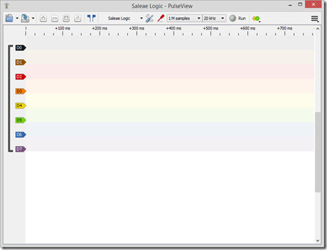
I then rebooted…and yesssss! There were now two SPI devices: /dev/spidev0.1 (SPI 0, CE 1), which is the hardware SPI peripheral using the second slave select and /dev/spidev32766.0 which I assumed was the spi-gpio device. Running lsmod showed me that the spi-gpio module was indeed loaded. I also tried a simple echo b > /dev/spidev32766.0 which didn’t return any errors, and connecting up my cheap logic analyzer also showed me that data was being written:

So there we go! If you need a second, not-so-fast SPI peripheral on the Pi you can try this out. You never know when having one will be handy. In theory you could create multiple of such devices each with its own GPIO selection, but I haven’t tried that out. [Edit: See the bottom of this post for info about this...]
To change the GPIOs used, you’d likely need to modify the .dts file, recompile it into a .dtb using the dtc program, then copy it to the /boot/overlays directory. This is provided you have the kernel and kernel modules on hand.
On a slightly related note: yeah, you can bitbang I2C as well. Ordinarily you might have needed to recompile the kernel to get the required kernel module but the default configuration that ships with Raspbian images already contains the kernel module. Next would be to specify which GPIO pins to use as SDA and SCL. To do this, you’d need to edit config.txt and add a dtoverlay directive to load the i2c-gpio-overlay.dtb file (which is already included in Raspbian). By default, i2c-gpio uses GPIO23 as SDA and GPIO24 as SCL, but you can override this behavior by adding parameters to the dtoverlay directive, like so:
dtoverlay = i2c-gpio-overlay,i2c_gpio_sda=6,i2c_gpio_scl=7
Where GPIO6 will then be used as SDA and GPIO7 will then be used as SCL.
Happy hacking!
Ps: Rather than having to recompile the .dts file every time you want to change the GPIO pins used, an __overrides__ section could be added in the .dts file which would ultimately let you specify the GPIO pins to be used similar to the way the i2c-gpio-overlay did it above. Its moderately straightforward and I just might try it out. You’d still need the spi-gpio modules though, mind..
Edit [6th December 2016] : A kind gentleman by the name of dvh has provided a sample DT overlay snippet for anyone who wants to have more than spi-gpio instance i.e more than one SPI bus, rather than one bus with several slave select lines. The snippet can be found here. Thank you dvh!
From my last post, I talked about the somewhat “edge” case where you’d want to add (cheap) Ethernet to a Raspberry Pi, probably the A+ or Zero as the case may be. I haven’t figured out the fixed MAC thing just yet, but I’m working on it. Anyways, after some time, another edge-edge case came to me: The ENC28J60 takes up the only SPI peripheral available on the Pi, so what if you needed to use both the ENC28J60 AND some other SPI device? The Pi’s SPI peripheral has two chip selects, so it is theoretically possible to use the exact same bus while using the first chip select for the ENC28J60 (which it uses by default) and using the second chip select for the other device. However, it goes without saying that network communications require some serious computing firepower so it might cause a bit of a performance hit in general. Thinking about it some more, it became apparent that the Pi should be able to bitbang SPI over GPIO. After tons of searching, I found this site that set me on the right path. I will try to walk you through the whole thing but having that open in another tab will be quite handy. And yes, I’m going to refer to it a whole lot. Apologies in advance.
In effect, the linux kernel (pauses reverently) has the ability to bitbang (i.e emulate) SPI over GPIO. The driver which makes this possible is called spi-gpio. The kernel must be explicitly compiled to enable this feature, however, so I had to set up a cross-compile environment for the Pi (which was an involved process, I tell ye), pull the kernel sources, (re-)configure the kernel to enable spi-gpio (the screenshots are provided at the link above), build the kernel, modules and device tree blobs, then copy the new kernel, modules and device tree blobs and overlays to the Pi. As mentioned, that is all covered in this page. For starters. What I’d acheived by doing all that was simply generating a the spi-gpio kernel modules, which I could then load at runtime (using modprobe or whatever). But, I needed a way to tell spi-gpio which GPIO pins specifically would be used to bitbang.
Enter Device Tree Overlays.
Device Trees are hierachical structures used to describe hardware. Typically the kernel would have been heavily dependent on manual modification to get it to run on a given target, which means that kernel code wouldn’t quite be portable. Or something. However, device trees have made it possible to separate the description of hardware from driver code, which eases development all round and centralizes hardware management. I know this is a vague explanation, but there are excellent resources on the net. Truth be told I’m still coming to terms with the whole thing myself. Amongst the uses of device trees is that they simplify the loading of drivers at runtime. However, because hardware varies, the concept of a device tree overlay was introduced. The overlay simply modifies an existing device tree by changing its existing contents or even adding new content. That way hardware descriptions can be built incrementally.
Relating this to the spi-gpio discussion, I needed to create a device tree overlay that would give the spi-gpio module certain information (the GPIOs to be used) and load it. The page I referenced included the device tree overlay but not for this particular purpose. Here’s what the file looked like:

As you can see, the highlighted portions are the portions of interest, where the MOSI, MISO, SCK and CS GPIOs are specified. The means by which he arrived at these values is covered on the page. However, the commented portion is of some concern here. This overlay..er…creates an SPI device using GPIO, but then loads the driver for a DS3234 Real-Time Clock over the SPI-GPIO device. This means that the device will be used exclusively by the RTC, which may not be what you want. In this case, I wanted access to the SPI device itself so I could write custom code from userspace i.e regular programs which could communicate over the SPI-GPIO device. The means by which such a thing is accomplished is using something else called SPIDEV, which is a user-space driver for SPI. SPIDEV is responsible for creating SPI device file entries in the /dev/ directory, which is what custom code would probably use. Think about it like this: custom code would most likely need access to the /dev/ entry e.g /dev/spidev0.0, and then your code would use open(), read(), write(), close() and maybe ioctl() calls to manipulate the device. Thus, we need to load this SPIDEV driver over the SPI-GPIO device so our custom programs can talk to it. As you guessed, all you’d need to do would be to completely remove the DS3234 part and uncomment the SPIDEV part from the above overlay. You’d also need to pick suitable GPIO pins as described on the page. Now that that’s done, you’d end up with something like this:

However, this is a device tree (overlay) source, which is like a .c file. To be of use we must convert it from a device tree source to a device tree blob (which is like what you get when you run gcc on your .c file). If you’re doing this on a Pi, you could apt-get install device-tree-compiler which will make it possible for the conversion to happen. However, I was doing this in my cross-compile environment. Luckily, building the kernel also built a working device tree compiler in the scripts/dtc/ subdirectory of the kernel source tree. I then took the Makefile from that page and modified it as follows:

Then I created a folder in my home directory, copied this Makefile and the overlay into it (the overlay was named spi-gpio-bitbang-overlay.dts) and also copied the dtc binary from scripts/dtc/ in the kernel source tree. So my folder contained these three files: dtc (the device tree compiler), Makefile (this Makefile) and spi-gpio-bitbang-overlay.dts (the overlay). I then ran Make as:
make DTC=./dtc
If I’d just run make, the computer would assume dtc was in my $PATH and try to find it and fail since it was not in fact in my $PATH. By specifying it this way, I’m forcing make to use the dtc in the current directory. There were some warnings but I got a spi-gpio-bitbang-overlay.dtb file which is what I really wanted. I copied that file to the /boot/overlays directory on the Pi. Remember that I’d also copied over the modules to /lib/modules/<kernel version>/ on the Pi. In a nutshell, the modifications made to the Pi were:
1) Replaced stock kernel with the one I built enabling spi-gpio support as a module.
2) The kernel build process produced the kernel modules needed. I copied the modules built from the cross compile environment to the /lib/modules/<new kernel version>/ directory on the Pi
3) Copied the .dtb file over to the /boot/overlays directory on the Pi.
Finally, I had to modify the /boot/config.txt file on the Pi to tell it to load this new overlay. This was done by adding the following lines to the end of the file:
dtoverlay=spi-gpio-bitbang-overlay
Yes, you can have multiple dtoverlay lines in config.txt (in mine one loads the ENC28J60 overlay, the second loads this). Note that the .dtb extension is not included. By adding this line, the modifications described by the overlay are applied to the base device tree (which is alot more complex), leading to the net result of creating the spi-gpio device and loading SPIDEV over that device. Automatically.
I then rebooted…and yesssss! There were now two SPI devices: /dev/spidev0.1 (SPI 0, CE 1), which is the hardware SPI peripheral using the second slave select and /dev/spidev32766.0 which I assumed was the spi-gpio device. Running lsmod showed me that the spi-gpio module was indeed loaded. I also tried a simple echo b > /dev/spidev32766.0 which didn’t return any errors, and connecting up my cheap logic analyzer also showed me that data was being written:

So there we go! If you need a second, not-so-fast SPI peripheral on the Pi you can try this out. You never know when having one will be handy. In theory you could create multiple of such devices each with its own GPIO selection, but I haven’t tried that out. [Edit: See the bottom of this post for info about this...]
To change the GPIOs used, you’d likely need to modify the .dts file, recompile it into a .dtb using the dtc program, then copy it to the /boot/overlays directory. This is provided you have the kernel and kernel modules on hand.
On a slightly related note: yeah, you can bitbang I2C as well. Ordinarily you might have needed to recompile the kernel to get the required kernel module but the default configuration that ships with Raspbian images already contains the kernel module. Next would be to specify which GPIO pins to use as SDA and SCL. To do this, you’d need to edit config.txt and add a dtoverlay directive to load the i2c-gpio-overlay.dtb file (which is already included in Raspbian). By default, i2c-gpio uses GPIO23 as SDA and GPIO24 as SCL, but you can override this behavior by adding parameters to the dtoverlay directive, like so:
dtoverlay = i2c-gpio-overlay,i2c_gpio_sda=6,i2c_gpio_scl=7
Where GPIO6 will then be used as SDA and GPIO7 will then be used as SCL.
Happy hacking!
Ps: Rather than having to recompile the .dts file every time you want to change the GPIO pins used, an __overrides__ section could be added in the .dts file which would ultimately let you specify the GPIO pins to be used similar to the way the i2c-gpio-overlay did it above. Its moderately straightforward and I just might try it out. You’d still need the spi-gpio modules though, mind..
Edit [6th December 2016] : A kind gentleman by the name of dvh has provided a sample DT overlay snippet for anyone who wants to have more than spi-gpio instance i.e more than one SPI bus, rather than one bus with several slave select lines. The snippet can be found here. Thank you dvh!

Almost a year later, but I found your article (and the one you referenced) very useful and I managed to get everything up and running. I am trying to enable multiple gpio SPI busses though, and I'm having a hard time getting this to work. The only way I seem to be able to create multiple SPI busses is by declaring more spidev nodes, each with a different chip select using 'reg':
ReplyDelete/dts-v1/;
/plugin/;
/{
compatible = "brcm,bcm2708";
fragment@0 {
target-path = "/";
__overlay__ {
spi1 {
compatible = "spi-gpio";
#address-cells = <0x1>;
ranges;
gpio-mosi = <&gpio 20 0>;
gpio-miso = <&gpio 19 0>;
gpio-sck = <&gpio 21 0>;
cs-gpios = <&gpio 26 1>, <&gpio 13 1>;
num-chipselects = <2>;
status = "ok";
spidev1{
compatible = "spidev";
reg = <0>; /* CE0 */
#address-cells = <1>;
#size-cells = <0>;
spi-max-frequency = <2000000>;
};
spidev2{
compatible = "spidev";
reg = <1>; /* CE1 */
#address-cells = <1>;
#size-cells = <0>;
spi-max-frequency = <2000000>;
};
};
};
};
};
Note that i had to declare multiple pins for cs-gpios. The plural naming tipped me off, but the rest of the pins are singular (gpio-mosi, gpio-miso gpio-sck) and 'num-mosi' etc don't seem to exist. I am probably misunderstanding the DTS format, but adding a second fragment (a duplicate of the first with different pins) results in a single port with the pins of the last fragment; the last fragment overrides the first one.
Do you have any idea on how to approach this?
Thanks
Hello dvh,
DeleteI'm glad to hear you found the article useful. I've never tried to do that before, so I'm not really sure. I do have one or two hypotheses though.
First, the rationale behind spi-gpio might be to provide another (single) SPI port, then different slave select pins which will be used to select the individual devices separately (i.e as in a multi-slave configuration), so those devices would share MISO, MOSI and SCK but each be controlled by their very own CS lines. In software, you would interact with those devices by manipulating the various spidev files corresponding to the devices on those slave select lines. This is fairly common since devices are supposed to be completely inert unless they are activated by their slave select signals.
With regards to the DTS format, I must confess that I personally find it baffling. Being an overlay, it would seem that adding another fragment would actually...overlay/obscure/override...any previous ones. I take it you used a different fragment number (e.g fragment@0, fragment@1) when you attempted this?
One thing to try might be to generate a single, large fragment containing the two spi-gpio instances. Device Tree Overlays look to be hierarchical structures, so perhaps you could have not one but two spi-gpio declarations in a single fragment? To illustrate what I'm trying to say, consider that we have a single fictitious spi-gpio instance as below:
/dts-v1/;
/plugin/;
/{
compatible = "brcm,bcm2708";
fragment@0 {
target-path = "/";
__overlay__ {
spi {
compatible = "spi-gpio";
#address-cells = <0x1>;
ranges;
gpio-mosi = <&gpio 1 0>;
gpio-miso = <&gpio 2 0>;
gpio-sck = <&gpio 3 0>;
cs-gpios = <&gpio 4 1>;
num-chipselects = <1>;
status = "ok";
spidev{
compatible = "spidev";
reg = <0>; /* CE0 */
#address-cells = <1>;
#size-cells = <0>;
spi-max-frequency = <500000>;
};
};
};
};
};
What I'm trying to say is, perhaps you could try making your fragment look like this instead:
/dts-v1/;
/plugin/;
/{
compatible = "brcm,bcm2708";
fragment@0 {
target-path = "/";
__overlay__ {
spi1 {
compatible = "spi-gpio";
#address-cells = <0x1>;
ranges;
gpio-mosi = <&gpio 1 0>;
gpio-miso = <&gpio 2 0>;
gpio-sck = <&gpio 3 0>;
cs-gpios = <&gpio 4 1>;
num-chipselects = <1>;
status = "ok";
spidev{
compatible = "spidev";
reg = <0>; /* CE0 */
#address-cells = <1>;
#size-cells = <0>;
spi-max-frequency = <500000>;
};
};
spi2 {
compatible = "spi-gpio";
#address-cells = <0x1>;
ranges;
gpio-mosi = <&gpio 5 0>;
gpio-miso = <&gpio 6 0>;
gpio-sck = <&gpio 7 0>;
cs-gpios = <&gpio 8 1>;
num-chipselects = <1>;
status = "ok";
spidev{
compatible = "spidev";
reg = <0>; /* CE0 */
#address-cells = <1>;
#size-cells = <0>;
spi-max-frequency = <500000>;
};
};
};
};
};
This includes two separate spi-gpio instances using completely different GPIOs for MISO and the other pins. I'm sorry its a long winded answer and is effectively a stab in the dark, but that's my best guess.
Kindly let me know how it goes. I'd love to hear your results.
Thanks for stopping by!
Hi M.,
DeleteThanks for the quick response, I had actually *just* figured it out myself and was about to post the working overlay here. Your last hunch was exactly right: putting multiple spi-gpio instances in the same fragment did the trick.
For reference I put my full overlay file here: http://pastebin.com/9eeu6H22
As you can see I am using 6 different SPI busses.
Hello dvh,
DeleteLooks like we were both spot on. That's great! Is it okay if I update the post and reference your sample overlay at the pastebin link? It'd be a useful resource for others with the same problem
Hi M.,
DeleteOf course that's no problem. I will also post this information in this thread https://www.raspberrypi.org/forums/viewtopic.php?f=44&t=166869&p=1076170
Hello dvh,
DeleteGreat, thanks! Best of luck with the project!
This comment has been removed by the author.
ReplyDeleteHi,
ReplyDeletethis page http://www.sciencegizmo.com.au/?p=105 is not more reachable.
Could you provide further info about it ?
Hello knip,
DeleteIt looks like the website is down or something. You can view the most recent snapshot of it (seemingly taken some time in 2019) here: https://web.archive.org/web/20191028070334/http://www.sciencegizmo.com.au/?p=105 .
Hope this helps.
I need to create a custom spi channel on Raspberry pi 5. Due to some reason the spi channel 0 is not generating clock signal. But Spi channel 1 works fine. In my project, I need 2 spi channels. Can somebody guide me in this? I am new to embedded development and this is part of my master thesis. I'm kind of stuck.
ReplyDeleteExcellent post, thank you so much! I've been contemplating the ability to use the Raspberry Pi to control 4 different DotStar LED strips, and looking for the ability to create software SPIs.
ReplyDelete