Enabling SPI1 on the Raspberry Pi B+/Zero/2/3
Me hearties,
Let us plunder and pil..
Sorry, wrong blog.
Ahem.
Hey all,
Its been a while. Been busy at work as usual, and haven’t really had much time to write much. As penance, I will post not one but two updates!
This particular post is in relation to Raspberry Pi users specifically. I had earlier talked about the vagaries involved in emulating SPI over GPIO in order to get an additional SPI peripheral. It was a moderately involved process, but the rewards were great
With the most recent release of the Raspbian Jessie distribution (2016-05-10), a number of improvements have been made to both the desktop parts and the “under-the-hood” parts, perhaps most significantly the kernel. This new release uses Kernel version 4.4, which now adds the ability to use the second hardware SPI peripheral, SPI1, on the Raspberry Pi. This is only available to devices with the 40-pin header (as seen from the title of this post) so users of the original model A and B will probably need to turn to spi-gpio should they need an additional SPI peripheral. This post aims to explain how to get SPI1 operational on the boards listed above.
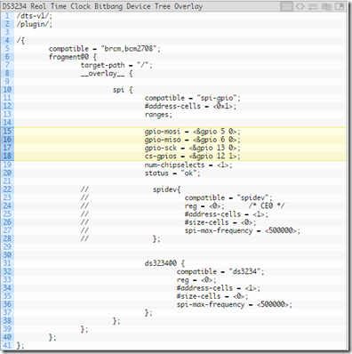
Enabling SPI1 is done using the Device Tree overlay method, which involves editing the /boot/config.txt file and adding a dtoverlay=xxxxxxx line/directive in there. However, the SPI1 peripheral apparently is capable of using 1, 2 or 3 chip select lines, so the particular overlay to be loaded depends on how many chip select lines you want. In most cases, you probably want a single chip select line so our dtoverlay directive will look like this:
dtoverlay=spi1-1cs
This will load the overlay giving us one chip select. And that’s it – no need to modify /etc/modules or anything like that. In fact, I didn’t even bother enabling SPI0, just this one, which means SPI0 and SPI1 can operate entirely independently of each other. Possibly raspi-config will someday be updated to support enabling SPI1 without having to edit /boot/config.txt directly. Once I rebooted, I now had a /dev/spidev1.0 file, corresponding to my newly-enabled SPI1 module.
The SPI1 pins are as follows (this page has a lovely pinout):
GPIO20 (Pin Header Number 38) – MOSI
GPIO19 (Pin Header Number 35) – MISO
GPIO21 (Pin Header Number 40) – SCLK
GPIO18 (Pin Header Number 12) – CE0
If you had wanted two chip selects, then the dtoverlay directive would have looked like this:
dtoverlay=spi1-2cs
This would let us use two chip select lines, where the first chip select line CE0 would be GPIO18 as above, and the second would be GPIO17 (Pin Header Number 11). For three chip selects the directive may be modified to become dtoverlay=spi1-3cs, where the third chip select line would be GPIO16 (Pin Header Number 36). Note that these are the default chip select lines used, but they can be re-routed to other GPIOs if they are not convenient. To do this, the dtoverlay directive would be modified to specify the particular GPIO (BCM numbers only, not pin header numbers!) as needed. For instance, to re-route the only chip select line used for the spi1-1cs overlay from GPIO18 to GPIO23 (Pin Header Number 16) , the directive would become:
dtoverlay=spi1-1cs,cs0_pin=23
For the other chip select combinations, similar parameters (cs0_pin, cs1_pin, cs2_pin) may be used. For more information, visit this page. Although I’ve not tested this, it is probably possible to specify these values on demand. For instance, if you were using three chip select lines and you only wanted to specify a different CE1 (leaving CE0 and CE2 at their default values) then your dtoverlay directive would probably look like this:
dtoverlay=spi1-3cs,cs1_pin=23
But as this is untested, I would not bet my life’s savings on it.
I also wanted to see how well SPI1 performed as opposed to the spi-gpio version I’d tested earlier. I know, it seems silly: software emulation/bitbanging is rarely ever a match for a hardware peripheral, but I like to think I’m a scientist at heart . So I fired up the logic analyzer and used a simple bash command (echo b > /dev/spidev1.0), then captured a couple of samples at a 1M sampling rate. The resulting traces are shown below:

Gosh, look how precise those clock edges are! The spi-gpio version didn’t look nearly so sexy, but it worked. 62 in hex is 98 in decimal, corresponding to the ASCII code for ‘b’. The 0A is likely the linefeed (LF) from the terminal. Here’s another one, this time showing the period of the SCLK pulses:

According to Pulseview, the clock pulses have a frequency of 500KHz, which is not too shabby. I expect that it supports higher speeds when properly configured so I wouldn’t worry too much about it. Oddly, I did notice a couple of glitches on the MISO line, seen below:

They’re the little spikes on the third line. My hypothesis is, since that line (Master In Slave Out) isn’t actually being driven by another peripheral (the Pi is connected to the Logic analyzer directly), there are tiny ‘noisy’ pulses that appear. If there was an actual element driving the line, that would probably not happen. Most importantly, when an actual SPI transaction is taking place (characterized by the chip/slave select line going low) the MISO line remains low throughout, so I don’t think this would be a problem.
So, if you have need of a second SPI peripheral, upgrade to the latest Raspbian and enjoy the goodness of hardware SPI. I can see how this would apply for using touchscreen devices (based on the ADS7846 chip) and other high-throughput devices (like nRF24L01+ radios or even ENC28J60 modules) simultaneously. Granted, some tweaking is needed, but that’s part of the fun innit?
Edit: For Pi 3 users, here's a thread on the Raspi forum that may be of some interest..
*wears eyepatch and tricorne*
Onward, ye readers!
Let us plunder and pil..
Sorry, wrong blog.
Ahem.
Hey all,
Its been a while. Been busy at work as usual, and haven’t really had much time to write much. As penance, I will post not one but two updates!
This particular post is in relation to Raspberry Pi users specifically. I had earlier talked about the vagaries involved in emulating SPI over GPIO in order to get an additional SPI peripheral. It was a moderately involved process, but the rewards were great
With the most recent release of the Raspbian Jessie distribution (2016-05-10), a number of improvements have been made to both the desktop parts and the “under-the-hood” parts, perhaps most significantly the kernel. This new release uses Kernel version 4.4, which now adds the ability to use the second hardware SPI peripheral, SPI1, on the Raspberry Pi. This is only available to devices with the 40-pin header (as seen from the title of this post) so users of the original model A and B will probably need to turn to spi-gpio should they need an additional SPI peripheral. This post aims to explain how to get SPI1 operational on the boards listed above.
Enabling SPI1 is done using the Device Tree overlay method, which involves editing the /boot/config.txt file and adding a dtoverlay=xxxxxxx line/directive in there. However, the SPI1 peripheral apparently is capable of using 1, 2 or 3 chip select lines, so the particular overlay to be loaded depends on how many chip select lines you want. In most cases, you probably want a single chip select line so our dtoverlay directive will look like this:
dtoverlay=spi1-1cs
This will load the overlay giving us one chip select. And that’s it – no need to modify /etc/modules or anything like that. In fact, I didn’t even bother enabling SPI0, just this one, which means SPI0 and SPI1 can operate entirely independently of each other. Possibly raspi-config will someday be updated to support enabling SPI1 without having to edit /boot/config.txt directly. Once I rebooted, I now had a /dev/spidev1.0 file, corresponding to my newly-enabled SPI1 module.
The SPI1 pins are as follows (this page has a lovely pinout):
GPIO20 (Pin Header Number 38) – MOSI
GPIO19 (Pin Header Number 35) – MISO
GPIO21 (Pin Header Number 40) – SCLK
GPIO18 (Pin Header Number 12) – CE0
If you had wanted two chip selects, then the dtoverlay directive would have looked like this:
dtoverlay=spi1-2cs
This would let us use two chip select lines, where the first chip select line CE0 would be GPIO18 as above, and the second would be GPIO17 (Pin Header Number 11). For three chip selects the directive may be modified to become dtoverlay=spi1-3cs, where the third chip select line would be GPIO16 (Pin Header Number 36). Note that these are the default chip select lines used, but they can be re-routed to other GPIOs if they are not convenient. To do this, the dtoverlay directive would be modified to specify the particular GPIO (BCM numbers only, not pin header numbers!) as needed. For instance, to re-route the only chip select line used for the spi1-1cs overlay from GPIO18 to GPIO23 (Pin Header Number 16) , the directive would become:
dtoverlay=spi1-1cs,cs0_pin=23
For the other chip select combinations, similar parameters (cs0_pin, cs1_pin, cs2_pin) may be used. For more information, visit this page. Although I’ve not tested this, it is probably possible to specify these values on demand. For instance, if you were using three chip select lines and you only wanted to specify a different CE1 (leaving CE0 and CE2 at their default values) then your dtoverlay directive would probably look like this:
dtoverlay=spi1-3cs,cs1_pin=23
But as this is untested, I would not bet my life’s savings on it.
I also wanted to see how well SPI1 performed as opposed to the spi-gpio version I’d tested earlier. I know, it seems silly: software emulation/bitbanging is rarely ever a match for a hardware peripheral, but I like to think I’m a scientist at heart

Gosh, look how precise those clock edges are! The spi-gpio version didn’t look nearly so sexy, but it worked. 62 in hex is 98 in decimal, corresponding to the ASCII code for ‘b’. The 0A is likely the linefeed (LF) from the terminal. Here’s another one, this time showing the period of the SCLK pulses:

According to Pulseview, the clock pulses have a frequency of 500KHz, which is not too shabby. I expect that it supports higher speeds when properly configured so I wouldn’t worry too much about it. Oddly, I did notice a couple of glitches on the MISO line, seen below:

They’re the little spikes on the third line. My hypothesis is, since that line (Master In Slave Out) isn’t actually being driven by another peripheral (the Pi is connected to the Logic analyzer directly), there are tiny ‘noisy’ pulses that appear. If there was an actual element driving the line, that would probably not happen. Most importantly, when an actual SPI transaction is taking place (characterized by the chip/slave select line going low) the MISO line remains low throughout, so I don’t think this would be a problem.
So, if you have need of a second SPI peripheral, upgrade to the latest Raspbian and enjoy the goodness of hardware SPI. I can see how this would apply for using touchscreen devices (based on the ADS7846 chip) and other high-throughput devices (like nRF24L01+ radios or even ENC28J60 modules) simultaneously. Granted, some tweaking is needed, but that’s part of the fun innit?
Edit: For Pi 3 users, here's a thread on the Raspi forum that may be of some interest..
*wears eyepatch and tricorne*
Onward, ye readers!
If you are using rapsberrypi 2 or 3 take a look to this tutorial -> https://tutorials.technology/tutorials/69-Enable-additonal-spi-ports-on-the-raspberrypi.html
ReplyDeleteFollowing those steps I managed to enable spi1 on rasp 2
Thanks for the info, raspen!
DeleteHave you actually tried two SPI devices? I'm running into issues with SPI modes. SPI1 only supports mode 0 and mode 2, but not mode 1 and 3. All the screens I can find run on mode 3...
ReplyDeleteErr, asides from enabling SPI1 and testing it using PulseView, I haven't actually tried two SPI devices. If you don't mind my asking, how did you determine that only modes 0 and 2 are supported?
DeleteIf you setup a loopback using SPIDEV you can see if a SPI port works. So I got it installed, set up the proper overlays, and tried to run the four modes individually with the loopback. Only two modes worked (and if memory serves me, they were 0 and 2). In fact, the processor returned some sort of error indicating an issues. I don't have the actual output on hand right now, as I ran the tests several months ago.
DeleteI was hoping someone else had seen the same issues and could confirm.
Thanks for the clarification! This thread seems to indicate that its a known problem: https://www.raspberrypi.org/forums/viewtopic.php?t=149981
DeleteThe screens you'd like to use, are they the SPI types that use the fbtft driver i.e ILI9341?